Overview :
An autonomous robot which can solve mazes of black lines on white background (or vice versa). Maze can have dead ends and intersections.
Hardware :
|
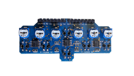
IR Sensor Array
6 IR sensors are used to detect the line. Basic concept behind this is that "white surfaces reflect light while black surfaces absorb it". |
|
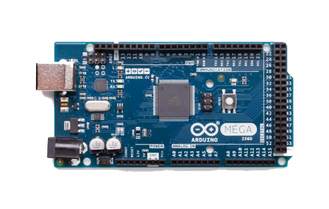
Arduino Mega 2560
Takes data from IR sensors and processes them to produce output for the motor driver. The DC jack on this Arduino can be used to directly provide power(voltage : 7 to 12 V DC) to it and also to other components. |
|
|
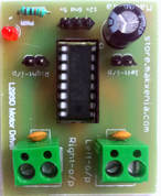
L293D Module
This is the motor driver unit and uses the L293D IC. Using this, we can drive 2 DC motors. It takes input from the Vin pin of the Arduino. |
|
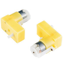
DC Motor
2 DC motors of 150 rpm were used. |
|
|
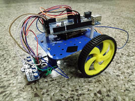
Chassis with wheels
Chassis is the frame of the robot. Wheels are mounted on the shaft of the DC motors and enable movement of the bot. Image shows all parts attached to the chassis. |
Working :
The maze solver uses the "Left Hand Algorithm" i.e. "by keeping one hand in contact with one wall of the maze the solver is guaranteed not to get lost and will reach a different exit if there is one".
The Arduino receives input signal from the manually calibrated IR sensor array. It then interprets this signal and determines the position of the line w.r.t. the bot and determines the appropriate speed and direction of rotation for the DC motors. It sends the appropriate signal to the motor drivers which then control the motor.
The motor speed is varied using PWM and line following is done using proportional control. Proportional control means assigning each sensor some weights depending on it's position and calculating the error i.e. sum of products of weights and sensor inputs. Then, speed proportional to the error is applied to the motors to obtain smooth line following.
Sharp turns could not be achieved using proportional control, so they were handled separately.
Checkout our code on GitHub
Team Members
Akshay Kulkarni
Aniket Gujarathi
Project done for Autobot competition in Axis '18, Technical Festival of VNIT, Nagpur.
Akshay Kulkarni
Aniket Gujarathi
Project done for Autobot competition in Axis '18, Technical Festival of VNIT, Nagpur.
